EXPLOSION ISOLATION FLAP VALVES – VIGIFLAP
Filtrowent International is the authorised regional representative of STIF company

INTENDED USE
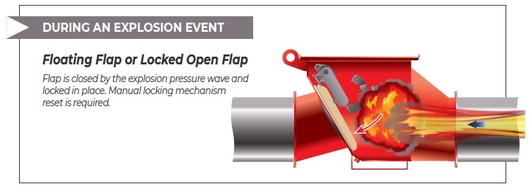
Explosion isolation flap valves are installed on pipelines on the dirty side of a dedusting system (before the dust collector), and their main task is to prevent the spread of explosion to other devices or to a production hall. In case of fire, the flap is closed by the shock wave which prevents the spread of the explosion to other parts of the system. The flaps are installed on pipelines at specified distance, thanks to which they work as a multilevel protection of a dedusting system.
The valve is kept in an open position by a lever arm. The valves can be used on both inlet and outlet of a protected device (e.g. dust collector), which enables the protected device from explosion. When an explosion occurs the flap closes instantly and blocks the explosion. The flap remains locked until it is unlocked manually.
BASIC CHARACTERISTICS
- Body: coated steel
- Flap: sst, round, convex
- Dimensions: ø160mm – ø800mm
- EPDM FDA gasket: -30°C to +70°C/14F° to 158F°
- Flanges: ISO and ANSI
- Inductive sensor: indicates the flap is in a locked position (non Atex)
OPTIONS
- Body: galvanised steel or stainless steel
- Silicone gasket: FDA and 1935/2004CE: -10°C to +180°C/14F to 356F,
- Counterflange,
- Atex 21 inductive sensors for indicating the locked position of the flap
- Capacity sensor indicating dust cummulation (max: 70°C/158F),
- Connection box installed to the valve body on the opposite side of the locking mechanism
CERTIFICATES
- INERIS 19ATEX0016X
- 2014/34/EU
- EN 16447
- EN 15089
- EN 1127-1
- EN 14460
- NFPA 69:2019
- INERIS 08ATEXQ406
- ISO9001:2015

DIMENSIONS & INSTALLATION DISTANCES
| VIGIFLAP DIAMETER (mm) | Minimal vessel volume | *Lmin (min installation distance) | **Lmin (min installation distance) | Lmax (max installation distance) | Download PDF |
| 160a | 1,35 m3 | 3,0 m | 5,0 m | 17,0 m | |
| 160b | 0,70 m3 | 4,0 m | 6,0 m | 17,0 m | |
| 180a | 1,35 m3 | 3,0 m | 5,0 m | 17,0 m | |
| 180b | 0,70 m3 | 4,0 m | 6,0 m | 17,0 m | |
| 200 | 1,35 m3 | 4,6 m | 6,6 m | 17,0 m | |
| 250 | 1,35 m3 | 4,0 m | 6,0 m | 17,0 m | |
| 300 | 2,90 m3 | 4,6 m | 6,6 m | 17,0 m | |
| 350 | 2,90 m3 | 4,2 m | 6,2 m | 17,0 m | |
| 400 | 4,50 m3 | 5,2 m | 7,2 m | 17,0 m | |
| 450 | 4,50 m3 | 4,7 m | 6,7 m | 17,0 m | |
| 500 | 6,05 m3 | 5,8 m | 7,8 m | 17,0 m | |
| 550 | 6,05 m3 | 5,5 m | 7,5 m | 17,0 m | |
| 600 | 7,65 m3 | 7,2 m | 9,2 m | 17,0 m | |
| 650 | 7,65 m3 | 6,7 m | 8,7 m | 17,0 m | |
| 700 | 7,65 m3 | 6,4 m | 8,4 m | 17,0 m | |
| 750 | 10,00 m3 | 7,3 m | 9,3 m | 17,0 m | |
| 800 | 10,00 m3 | 6,9 m | 8,9 m | 17,0 m |
* Flap valve opened by the air flow, valve in horizontal position.
** Flap valve kept open, with elbows, valve in vertical position.
SPECIFICATION
| Kst max | ≤ 250 bar.m/s |
| Kst min | no limit |
| Pmax | 10 bar |
| MIE | ≥ 10 mJ |
| MIT | ≥ 400°C |
| MESG | 1,7 mm |
| Pred max* | ≤ 0,5 bar |
| Resistance | 2,0 bar |
| Marking | EX II D |
| Atex inside | Zone 20 (II 1D) |
| Dust** | all kinds of dust |
| Dust concentration | no limit |
| Air flow velocity | Clean air side: ≤ 30 m/s Dirty air side: ≤ 45 m/s |
| Working mode | Clean air flow Dirty air flow |
| Air flow range | Pull flow Push flow |
| Working pressure | 500 mbar max |
| Working underpressure | -800 mbar max |
| Elbow quantity | No limit |
* Vessel (potential ignition source)
** Organic dust, synthetic dust or metal dust
TESTS OF VIGIFLAP PREFORMED AT THE NOTIFIED BODY INERIS
OTHER FEATURES OF EXPLOSION ISOLATION FLAP VALVE
VIGIFLAP WORKING MODES
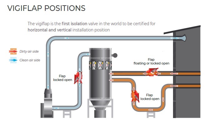
INSTALLATION
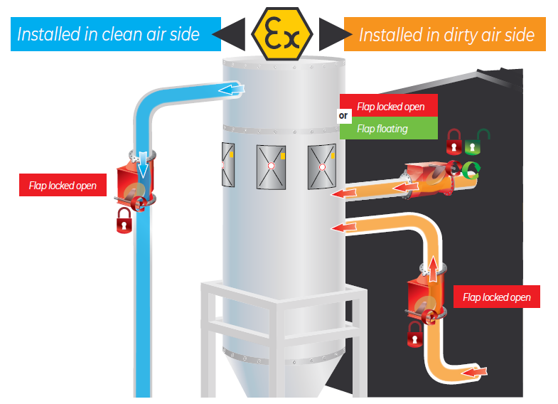
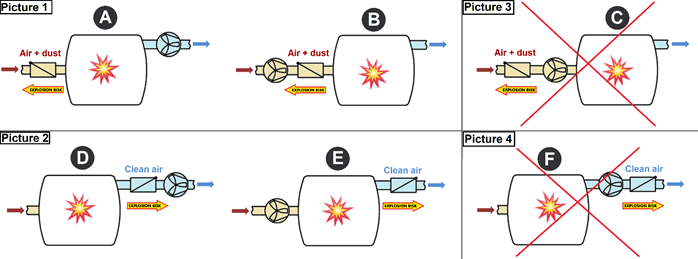
The flap valves we offer are applicable for both pull and push air flow modes. The flap valves can be installed on the dirty air side (see positions A and B in Drawing 6, Picture 1) or on the clean air side (see positions D and E in Drawing 6, Picture 2) with the valve blocked in an open position with the use of the installed mechanism.
The working air flow (push or pull) has no influence on the minimal installation distance.
Positions C and F are not allowed (Drawing 6, Pictures 3 and 4).
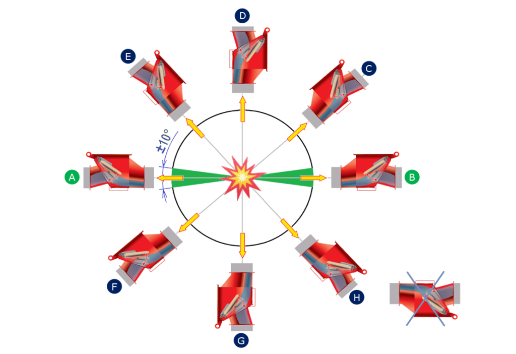
The valve can be installed in various orientations – in Drawing 7 you can see the allowed orientations of the valves for horizontal and vertical installations. Positions A and B are correct providing the valve is in a horizontal position ± 10°.
Positions C, D, E, F, G and H are correct providing the valve is installed in an angled or
vertical position (greater than ±10°).
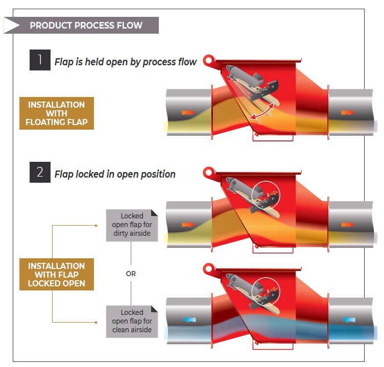
Positions A to E & B to C – with 2 posibilities of work:
- flap in floating position
so, it’s open by the air flow. - flap is kept open by the
mechanic system, so it’s
always open.
Positions C to D & E to D
- Always work with flap kept open by gravity.
Positions A to G and B to G
- Always need to work with flap kept open by mechanic system, so it’s always open (if not pressure drop is too high).
When selecting an explosion isolation flap valve pay attention to the following aspects:
- the valve certification validity togehter with the explosivity class it is intended for (St 1, St2 or St3)
- the allowed minimal installation distance and the limit of bends (elbows) between the dust collector inlet and the flap valve (this information is alwys indicated in the instruction manual but it has to be checked before purchasing the valve)
- the working system of the dust collector: overpressure (push system) or underpressure (pull system) in order to install the flap valve correctly
- other recommendations for the flap valve installation such as: piping installation on the protected side, correct positioning of the valve on the piping etc.
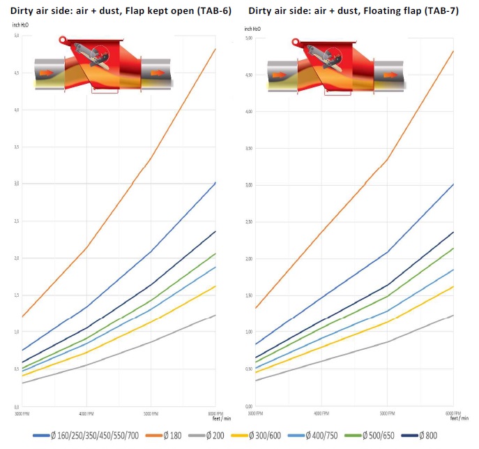
AERAULIC PRESSURE DROPS