Explosion isolation flap valve – ATEX protective system
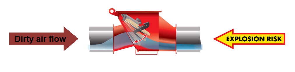
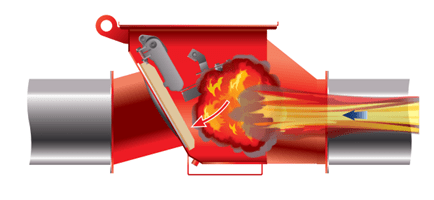
Flap valves are installed on pipes on the dirty side of the dedusting system (before the dust collector), and their main task is to prevent the spread of explosion on other devices or to a production hall.
In case of fire, the flap is closed by the shock wave which prevents the spread of the explosion to other parts of the system. The flaps are installed on a pipeline, at a specified distance, thanks to which they work as a multilevel protection of a dedusting system.
It is important to pay attention to the following issues when deciding on a given flap valve type:
- check the certificate validity of the flap valve and the dust explosivity class the valve is designed for (st1, st2, st3)
- check the distance and number of bends allowed between the dust collector inlet and the flap valve (this information is always given in the user manual, but these data should be checked before purchasing and installing a valve).
- check the flap valve mounting method as it depends on the dust collector working system, that is, whether the flap is going to be installed on the collector working in overpressure (PUSH flow – pressure air flow) or in negative pressure (PULL flow – vacuum air flow system)
- check other mounting conditions of the flap valve such as: requirements on piping mounting on the protected side, correct location of the flap in the pipeline etc.
Installation of the explosion isolation flap valve
The flap valves are certified to work with vacuum air flow (Pull flow) or pressure air flow (Push flow). They can be installed in position A and B (picture 1) on the dirty air side or in position D and E (picture 2) on the clean air side. In position D and E the flap valves need to be blocked in an open position with the mechanical system.
The working direction of air flow (Push flow or Pull flow) has no influence on the min installation distance. The working position D and E are recommended for turning the clean air back into the workhouse. It is recommended not to use positions C (picture 3) and F (picture 4).
Picture 1. The position of flap valve installation in the system
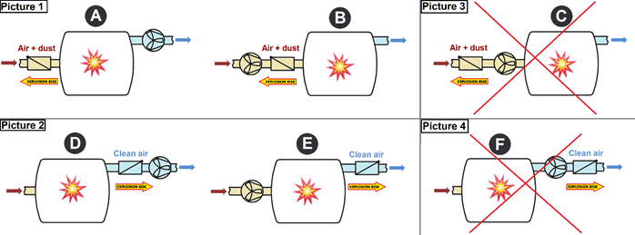
Legend: 1 – Explosion isolation flap valve; 2 – protected device (eg. dust collector); 3 – extraction fan
The picture below (Picture 2) presents the allowed horizontal and vertical orientations of the valve V-Flap series.
Positions A and B are correct for the V-Flap valve if it is installed in a vertical position at ± 10°.
Positions C, D E, F, G and H are correct for the V-Flap valve if it is installed in a horizontal position at more than ± 10°.
Picture 2. The allowed horizontal and vertical orientations of the valve V-Flap series
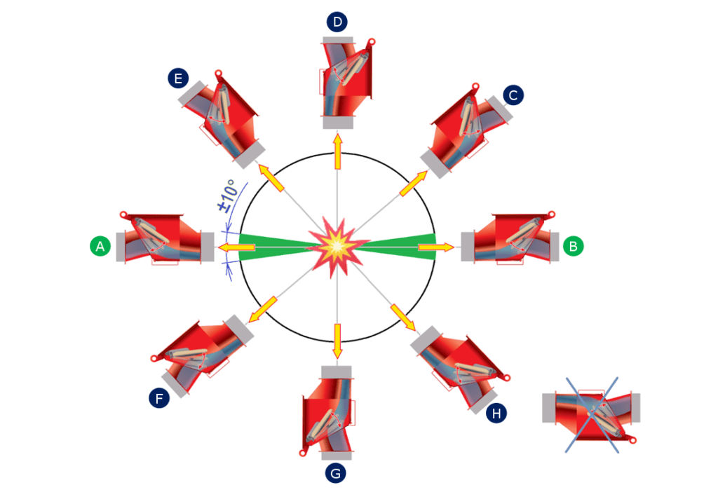
Position A to E & B to C – there are 2 working options: flap valve in a floating position – opened by air flow OR flap valve kept open by a mechanical system – always open.
Position C to D & E to D – always works with a flap kept open by gravity.
Position A to G & B to G – always needs to work with a flap valve kept open by a mechanical system
